")
")
The enormous development of electronics over the past decades has also affected our homes. The term Smart Home is no longer a stranger to anyone. Home Assistant undoubtedly has its place among the various Smart Home systems.
Home Assistant  is an open-source platform for home automation (smart home), which allows centralized control of various smart devices from various manufacturers and is intended primarily for tech enthusiasts who want to have full control over their smart home system, for those who have devices from different brands and want to connect them, for users who prefer a local solution to the cloud, therefore in my case, for these reasons, the choice fell on Home Assistant. Few people start with Smart Home elements, so to speak, on a green field, and each of us has some device with smart features at home, whether it is a TV, a multimedia player, a table lamp or a vacuum cleaner. I myself gradually connect various components to the Smart Home system, whether new devices or existing ones. The garage door has also become such an element. The main requirements of the solution were: minimal interference with the gate control hardware, which has been operating reliably for many years, maintaining the autonomy of control and the requirement to maintain functionality in the event of a failure of the Smart Home system or its elements, and maintaining the level of security.
 Based on these requirements, the choice was made to access the gate control using another remote control connected to the Home Assistant system. This solution is universal and does not depend on the type of gate control unit. In my case, it was a Nice device, operating in the 433MHz band with a rolling code..
The device allows you to control your garage door from a mobile phone, or other Home Assistant Smart Home control panel using the built-in remote control and monitor the basic positions of the door. The core of the device is the NodeMCU ESP-12E, which is a popular development board based on the ESP8266 microcontroller.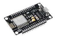 However, it’s over ten years old and is quite lacking in terms of built-in hardware peripherals. Is reccomended to use an ESP32-C3 when you’re thinking you need to use an ESP8266 because the ESP32(-Sx) is “too powerful” or “overkill”, it does not meet the requirements of Made for ESPHome. The original NodeMCU, D1-Mini and ESP-01 are examples of boards which utilize an ESP8266; note that there are (pin-compatible) versions of these boards available which instead utilize a more modern ESP32 or variant. Anyway I have it in the drawer, and why do not use it , if work stable ?
The ESP8266 uses the Tensilica Xtensa LX106 core, which is 32-bit in terms of instruction set, but has a 16-bit data bus (therefore sometimes referred to as a "16/32-bit hybrid"). It can work with 32-bit data, but some operations may be less efficient than on full-fledged 32-bit chips (e.g. ESP32). I used a development board to avoid implementing the module in SMD technology, which would be necessary if using a separate processor, moreover, it would be uneconomical, because this development board can be purchased for 5€ and contains the necessary circuits for power supply, USB communication, indicator LEDs, reset and boot buttons and auxiliary circuits. The choice to use a development module will allow implementation in amateur conditions even for less experienced radio amateurs, because pins are soldered around the perimeter of the board, which serve as leads for integrated circuits and allow mounting on a PCB or connecting wires for testing.
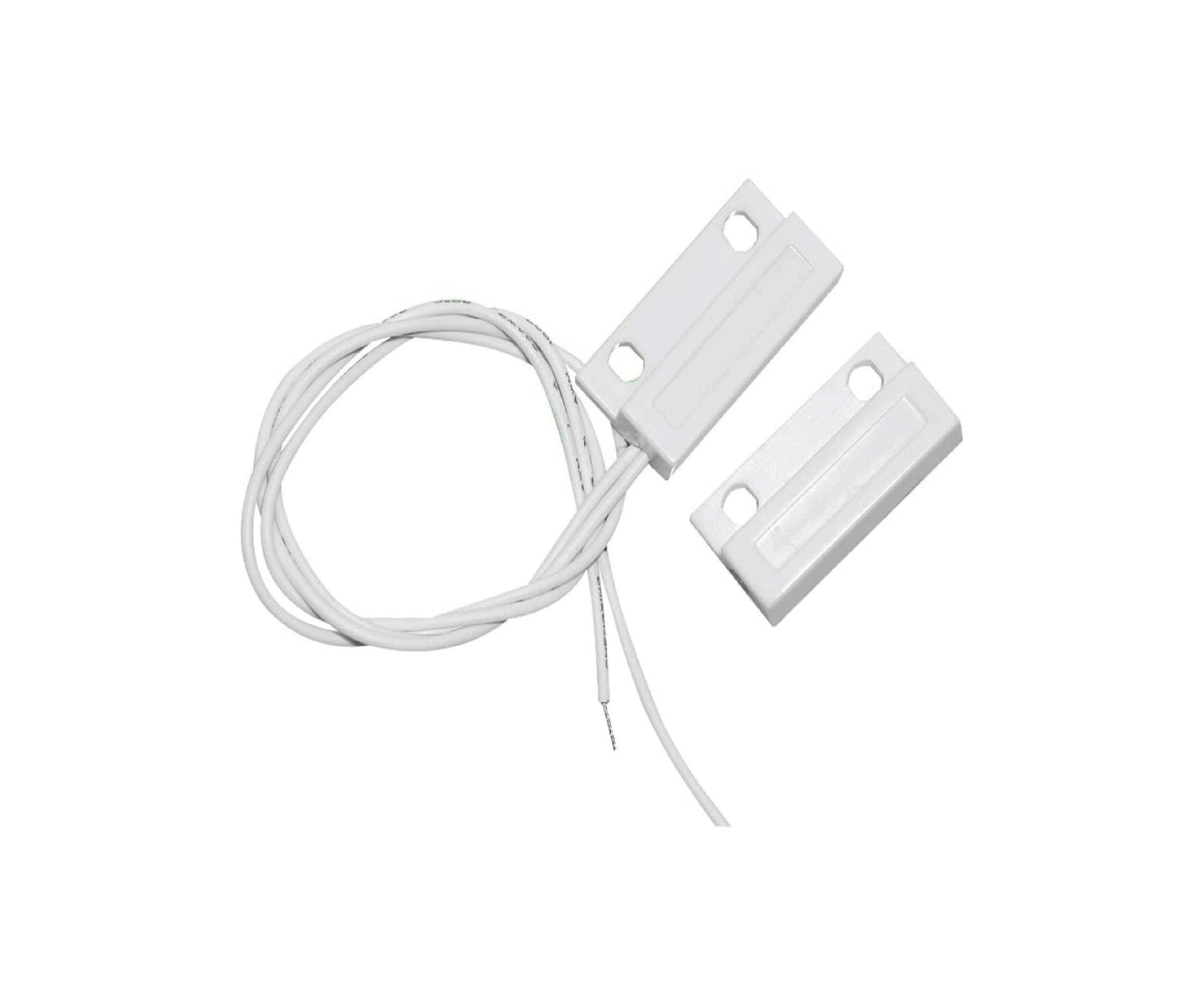
Here is the device wiring diagram : The U2 circuit in the diagram represents the nodemcu 12-E development module, which contains 4MB of flash memory for the program, 96kB of RAM, a wifi module 802.11 b/g/n (2.4GHz band) and several universal inputs/outputs. It communicates with the Home Assistant using the built-in Wifi module. Magnetic sensors SW1 and SW2 of the MC-38 type are connected via connector X1 to monitor the opening/closing status of the gate. The circuits are powered from a 5-volt source supplied via the USB input on the development board, or via terminals X1:1 and X2:2 of connector X1. The transmission of codes in the 433MHz band is provided by the U1 FLO2R-S transmitter circuit. The finished transmitter module
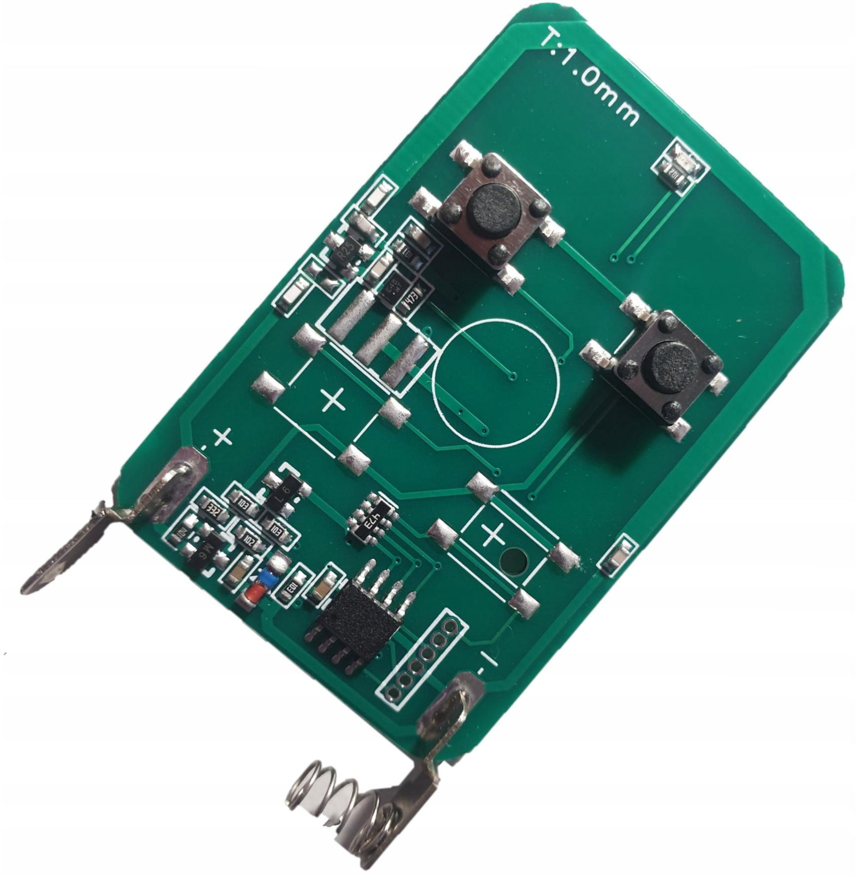
 I bought it as a spare part for about €10. I used four wires to bring the required signals from the printed circuit board to the JST connector X2. GND to pin x:5. I connected the 3V power supply of the remote control module via pin X2:1 to pin number 4 of the integrated circuit on the PCB. There is only one, so it is easy to identify. I connected the switches K1 and K2 to X2:2 and X2:4, as is clear from the wiring diagram. The microcomputer communicates with the Home Assistant via a wireless wifi network. The received command for simulated switching on by pressing the appropriate button of the FLO2R-S controller sets a high level at the output D7 or D8 of the microprocessor, which causes the transistor Q1 or Q2 to turn on. The collector of the transistors is connected in parallel to the buttons K1 and K2 on the printed circuit board of the remote control. Resistors R1 to R4 ensure base current limitation and reliable switching off of transistors Q1 and Q2. Input signals from gate position sensors SW1 and SW2 are fed through connector X1 to processor inputs D1 and D2. The necessary high input level is provided by pull-up resistors built into the ESP8266 processor. Their state is transmitted to Home Assistant for status display, or for automation scripts.
The mechanical arrangement of the individual elements is clear from the following figure: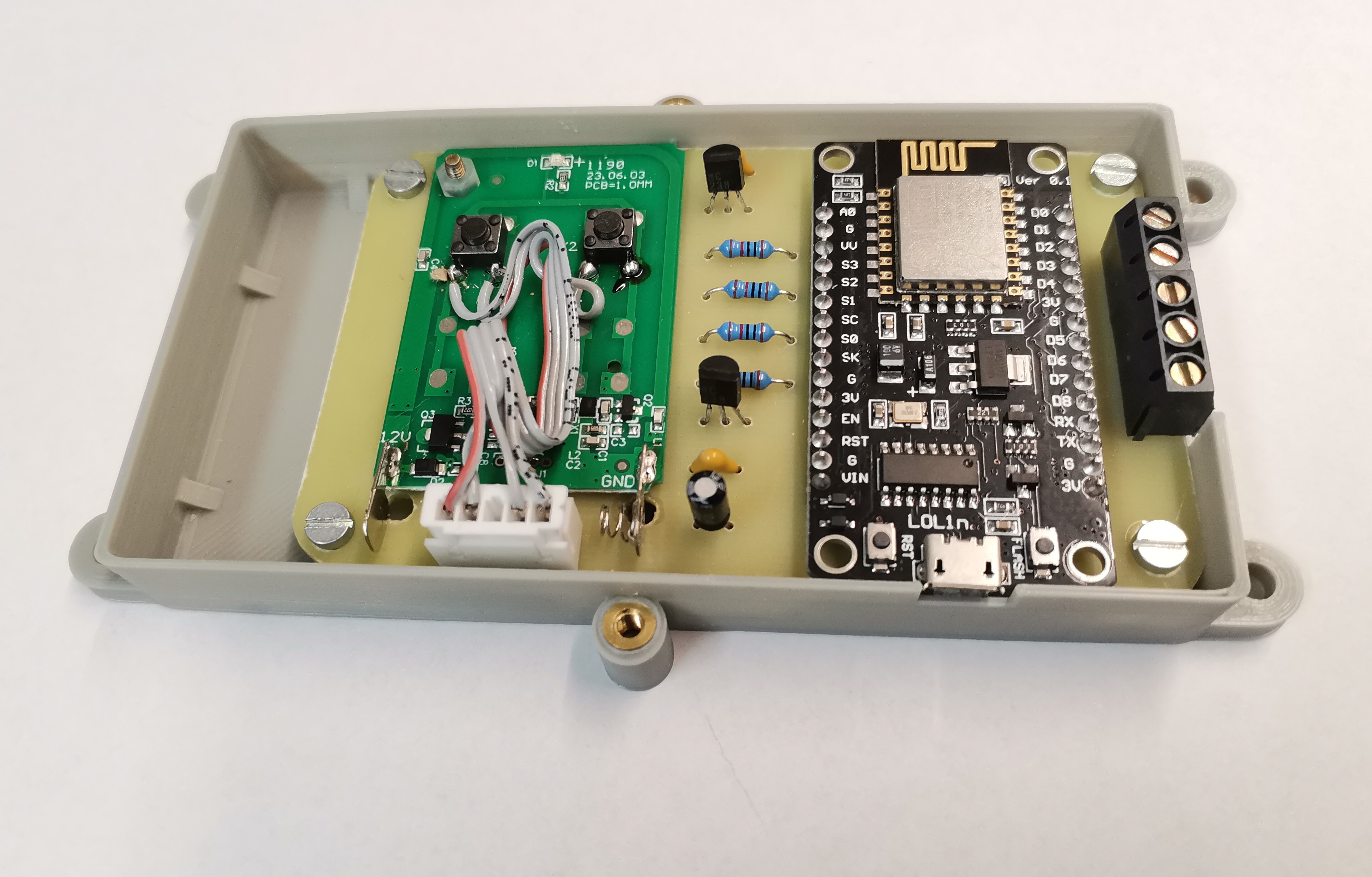
All components are mounted on the LK-24 printed circuit board, the layout of the printed circuit board components is shown in the following figure. The mounted printed circuit board is placed in a plastic box made on a 3D printer. After mounting the LK-24 printed circuit board and uploading the firmware package to the microcontroller, there is no need to make any further settings, you are done. 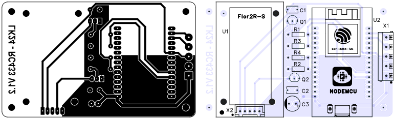
The necessary firmware is created using ESPHome. ESPHome is a system that allows you to turn ordinary microcontrollers into smart home devices. It uses YAML configuration files and, based on the contents of these files, creates its own firmware, which you can then install directly on your device. The hardware defined in the configuration - such as sensors, switches, lights, etc. - automatically appears in the Home Assistant user interface, or can be accessed via a simple web user interface or MQTT. For Home Assistant, ESPHome is available as an integration, and once installed in Home Assistant, the ESPHome device manager is available on port 6052 at the corresponding Home Assistant IP address. When creating a new RC433 device and after the initial initialization, I edited the configuration file , it contains all the necessary commands to generate the firmware in the device manager environment .
The content of the configuration YAML file looks like this:
esphome:
name: rc433
friendly_name: RC433
esp8266:
board: nodemcuv2
# Enable logging
logger:
# Enable Home Assistant API
api:
encryption:
key: " yours 32 bit key used by ESPHome integration inside HomeAssistent"
ota:
- platform: esphome
password: "8f04097f130743c53caa1a918a23b6da"
wifi:
ssid: name of Your Wifi network
password: password for Your Wifi network
# Enable AP hotspot, if connection to Your network fail
ap:
ssid: "Rc433 Fallback Hotspot"
password: "1234567890"
captive_portal:
# example of switch configuration
switch:
- platform: gpio
pin: GPIO13
id: swK2
name: "switch K2"
icon: "mdi:gate"
on_turn_on:
- delay: 600ms
- switch.turn_off: swK2
- platform: gpio
pin: GPIO15
id: swK1
name: "Switch K1"
icon: "mdi:gate"
on_turn_on:
- delay: 600ms
- switch.turn_off: swK1
# input sensors section
binary_sensor:
- platform: gpio
pin:
number: GPIO4
inverted: true
mode:
input: true
pullup: true
name: sw Close
- platform: gpio
pin:
number: GPIO5
inverted: true
mode:
input: true
pullup: true
name: sw Open
 After saving the configuration and pressing the install button, the firmware of the new device is compiled based on the commands in the YAML file, which is uploaded via wifi or via a USB cable to the device in the next step. This firmware, through the integration of ESPHome, ensures that the switch in the Homeassistant generates a 600ms pulse, simulating pressing a button on the FLO2R-S remote control, and is able to
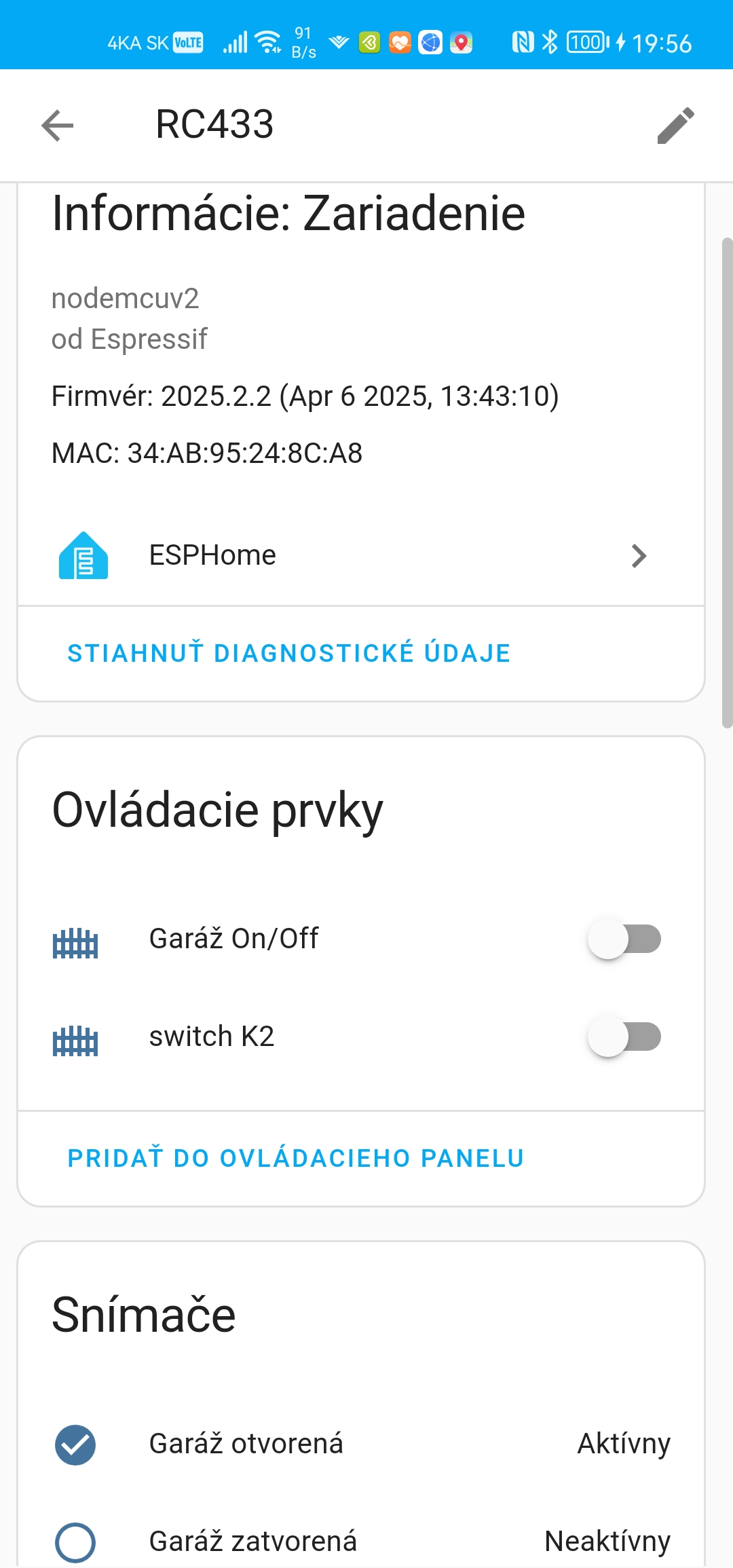
You can download all the necessary files for the implementation of the device from the relevant download section.
Used components:
C1,C2 100nF /50V
C3 10uF /50V
Q1,Q2 BC238
R1,R2,R3,R4 10k
SW1,SW2 MC-38
U1 FLO2R-S
U2 NODEMCU(12E)
X1 DB301V-5.0-5P-BU-S
X2 ZX-XH2.54-5PZZ
Usfull links:
https://www.home-assistant.io/
https://esphome.io/
https://techfun.sk/produkt/vyvojova-doska-node-mcu-esp12-e-v3-0-ch340g/
https://allegro.sk/produkt/dialkovy-ovladac-na-dvere-garazovych-bran-ako-nahrada-za-nice-flo2r-flor-2-kanaly-433-mhz-e2e1633c-1913-4d5f-abe3-e482be0f15bf?offerId=17725684650&utm_feed=547ce2b2-2e28-4773-9707-58218068540e&utm_source=google&utm_medium=cpc&utm_campaign=SK%3EHome%3EBuilding%3E3P%3EPMAX&ev_campaign_id=21056415822&gad_source=1&gad_campaignid=21063220922&gbraid=0AAAAAqKvbIhJqLvOBV69Y3klkROMHFNb6&gclid=CjwKCAjwlaTGBhANEiwAoRgXBXkI8hRkpQ_BDJkC_qV5orWxmSLnm4_aCzhxmu86hLEaWknd2LekSxoCABMQAvD_BwE
Note: The FLO2R-S remote control module can be replaced with any other similar remote control that your device uses.