")
")
Reflow oven
Hits: 182
The huge boom in the production of electronics and its components also affects the work and creation of radio amateurs. New components bring new possibilities by improving functionality and expanding their capabilities. The reduction of chip sizes comes hand in hand with the reduction of case sizes and the introduction of new types. The vast majority of new parts and new cases are designed for SMT (Surface Mount Technology). The use of such components in radio amateur practice brings many pitfalls, one of which is soldering.
For repairs, we can use a hot-air gun for soldering or desoldering individual parts, but when trying to solder a larger number of parts, the problem of error rate, cleanliness of soldering and ultimately the resulting reliability arises. This problem is partially solved by the described device. The goal was to make a device that would enable soldering of SMD ( surface-mounted device) components using a controlled temperature course. Of course, affordability was also an important parameter, even though the possibility to buy a ready-made soldering furnace is endless..
Hardware decription:
As the basis of my device, I used a commonly available commercial oven for baking pizza, fries, etc. When choosing the device, the size, price and performance of the heating coil were the decisive parameters. I chose the Calcone 73043 mini baking oven ,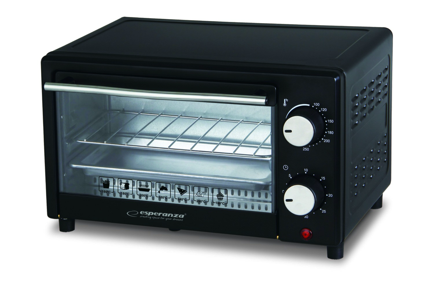 with an internal space of 24cm x 20cm, which is also the maximum size of the printed circuit board. The power of the heating spiral is 900 watts, which will ensure a sufficiently steep temperature rise to ensure the necessary thermal course of soldering. Wiring diagram is on the previous picture .
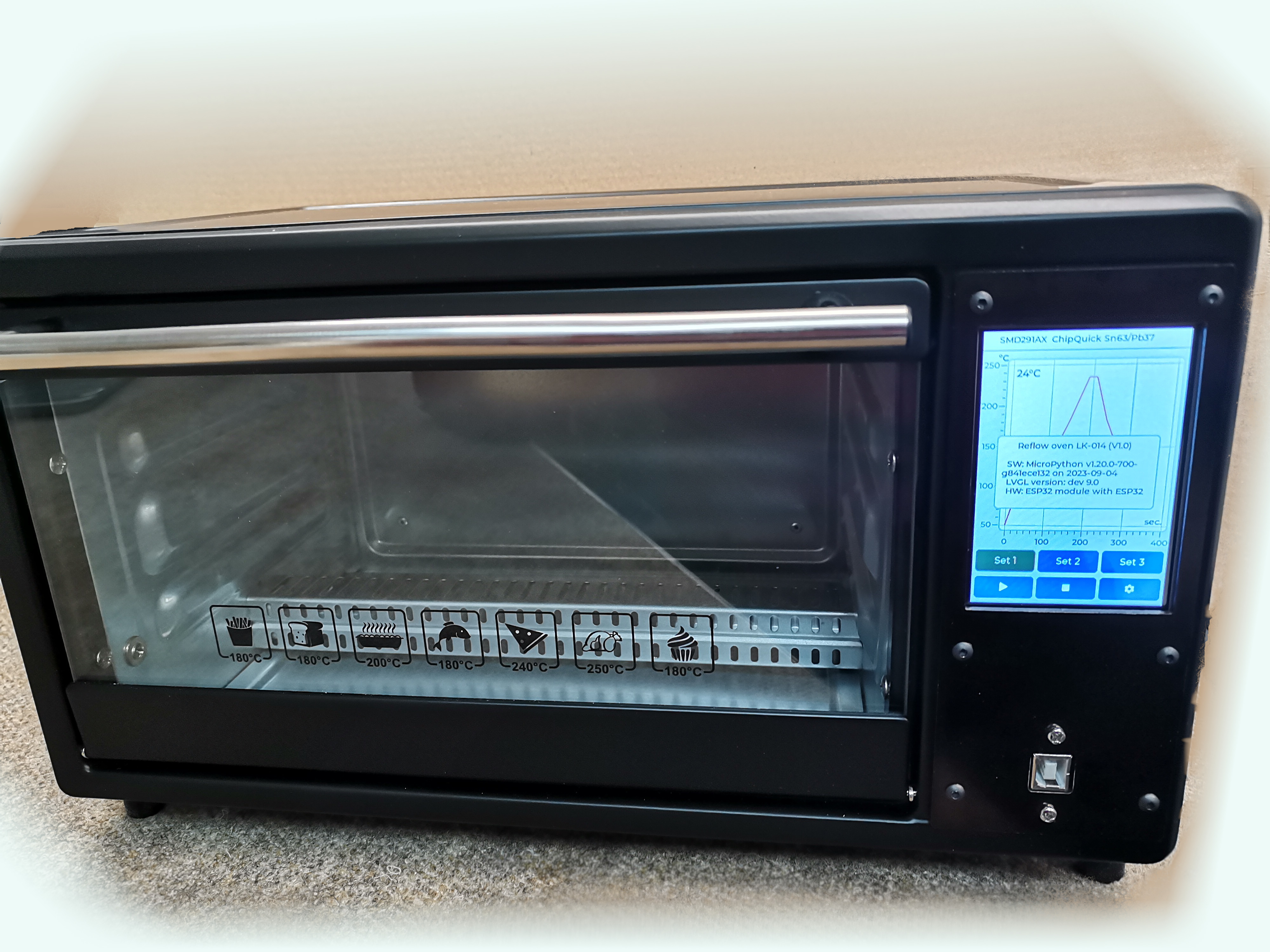
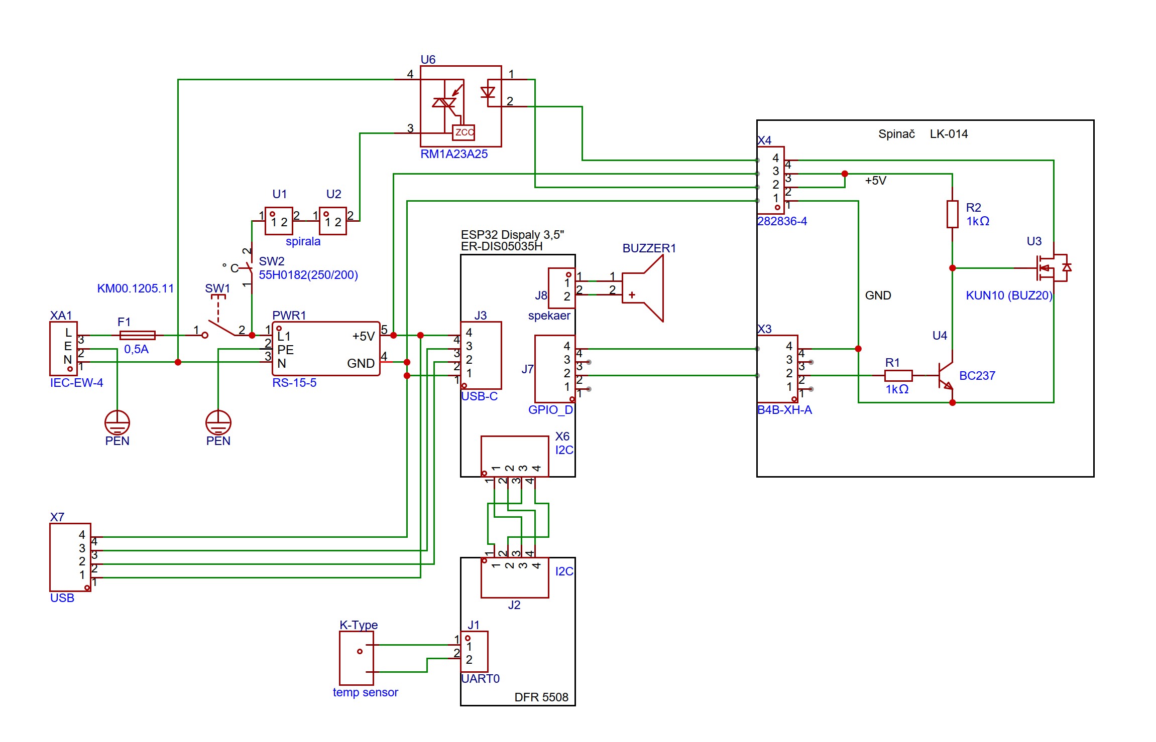 The device is connected to the electrical network via the XA1 socket, the body of which also contains the fuse F1 and the main switch SW1. A power supply PWR1 is connected behind the main switch SW1, which provides a 5V power supply for all low current mini oven circuits. The control part is provided by a touch screen with a built-in 32-bit ESP32 processor, all low-current circuits of the mini oven. The control part is provided by touch display with built in 32-bit microprocessor ESP32 .
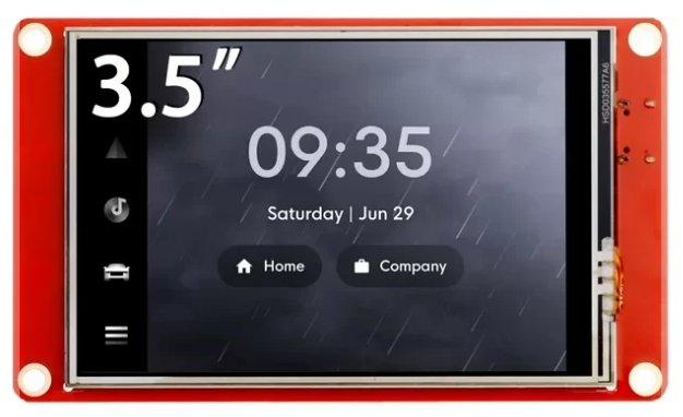 Temperature measurement in the chamber is provided by the DFR 5508 module with a K-type thermocouple.
 The thermocouple itself is in a metal case, which is supposed to protect it mechanically, but the thermal inertia of the case is so high that it is unusable for this purpose, due to the high thermal inertia, and it is necessary to remove the thermocouple from the case, or use another suitable type without a case. I used another, commonly available, K-type thermocouple without a case at a price of approximately €1.50. I placed the thermocouple in the upper right part of the chamber and inserted it into the rivet nut and secured it with a small flange on the outside.
 The connection and communication of the ESP32 microcontroller contained in the ER-DIS05035H touch screen and between the DR5508 thermocouple module is via the I2C bus. A small speaker, commonly used in PCs for acoustic signaling, is also connected to the display module via the J8 connector. The output signal from the ESP32 microcontroller is fed to the LK-014 switch board via the J7 connector. The heating coil is marked as U1 and U2 on the diagram, because it consists of 2 parts, located in the upper and lower parts of the heating chamber. It is controlled by the switching element U6, which is an opto-electronic element with a triac switching at the time of the transition of the alternating voltage to zero, for the reduction of electromagnetic interference during switching and opening of the electronic element, since when the voltage is zero, the current is also logically zero and electromagnetic interference cannot occur. However, since it is not an ideal electronic element, switching at zero does not occur, so the level of electromagnetic interference will also be different from zero, but very low, and additional filter circuits are not needed to suppress electromagnetic interference into the electrical network, so that the device meets EMC requirements. ( Electromagnetic compatibility). The RM1A23A25 coil switch, marked as U6 on the diagram, is controlled by a voltage of 3V to 30V DC, but the current carrying capacity at the output of the ESP32 microcontroller is not sufficient for direct control of this element, therefore the LK-014 switch is added to the circuit, to ensure increased current carrying capacity of the microcontroller output, so that it can safely control the switching element U6. The power of the spiral is controlled by pulse width modulation of the corresponding output, which is controlled by the switching element U6 .
 The LK-014 switching circuit is powered by 5 volts from the PWR1 source and is controlled by the output voltage of the microcontroller 0V to 3V, and the level of 5 volts at the output of the LK-014 switch will ensure safe control of the U6 element with sufficient current. The LK-014 switch circuit contains a BC 237 transistor marked as U2 on the diagram and a power switching FET transistor BUZ20 or similar with Ut in the range of 1V to 4V, I used an old stock KUN10, marked as U1. Connection is very trivial. The width-modulated output from the micro-controller takes on values of 0V or 3V. If there is a value of 3V at the output of the micro-controller, i.e. a logical unit, the transistor U2 is excited through the resistor R1 and it is turned on, which causes a voltage drop at the gate of the FET U1 to close it, so that it does not flow through the driving LED diode of the element U6 no current. Otherwise, the state of 0V at the output of the micro-controller will cause that the transistor U2 is not driven by any current through the resistor R1, which will close the transistor U2 and the voltage on the gate of the transistor u1 will rise to 5V, which will open the led of the element U6. which leads to the switching of the triac inside the opto-relay and to the excitation of the heating coil. The placement of the LK-014 printed circuit board and the pattern of the printed circuit board is shown in the following picture..
  The SW2 thermostat provides protection against any malfunction of the regulator, with the fact that, in an uncontrolled state, when a temperature higher than 250°C is reached, it will be disconnected and therefore the heating coil will be disconnected from the power part of the circuits, and the function will only be restored when the temperature drops below 60°C.
with an internal space of 24cm x 20cm, which is also the maximum size of the printed circuit board. The power of the heating spiral is 900 watts, which will ensure a sufficiently steep temperature rise to ensure the necessary thermal course of soldering. Wiring diagram is on the previous picture . The device is connected to the electrical network via the XA1 socket, the body of which also contains the fuse F1 and the main switch SW1. A power supply PWR1 is connected behind the main switch SW1, which provides a 5V power supply for all low current mini oven circuits. The control part is provided by a touch screen with a built-in 32-bit ESP32 processor, all low-current circuits of the mini oven. The control part is provided by touch display with built in 32-bit microprocessor ESP32 . Temperature measurement in the chamber is provided by the DFR 5508 module with a K-type thermocouple. The thermocouple itself is in a metal case, which is supposed to protect it mechanically, but the thermal inertia of the case is so high that it is unusable for this purpose, due to the high thermal inertia, and it is necessary to remove the thermocouple from the case, or use another suitable type without a case. I used another, commonly available, K-type thermocouple without a case at a price of approximately €1.50. I placed the thermocouple in the upper right part of the chamber and inserted it into the rivet nut and secured it with a small flange on the outside. The connection and communication of the ESP32 microcontroller contained in the ER-DIS05035H touch screen and between the DR5508 thermocouple module is via the I2C bus. A small speaker, commonly used in PCs for acoustic signaling, is also connected to the display module via the J8 connector. The output signal from the ESP32 microcontroller is fed to the LK-014 switch board via the J7 connector. The heating coil is marked as U1 and U2 on the diagram, because it consists of 2 parts, located in the upper and lower parts of the heating chamber. It is controlled by the switching element U6, which is an opto-electronic element with a triac switching at the time of the transition of the alternating voltage to zero, for the reduction of electromagnetic interference during switching and opening of the electronic element, since when the voltage is zero, the current is also logically zero and electromagnetic interference cannot occur. However, since it is not an ideal electronic element, switching at zero does not occur, so the level of electromagnetic interference will also be different from zero, but very low, and additional filter circuits are not needed to suppress electromagnetic interference into the electrical network, so that the device meets EMC requirements. ( Electromagnetic compatibility). The RM1A23A25 coil switch, marked as U6 on the diagram, is controlled by a voltage of 3V to 30V DC, but the current carrying capacity at the output of the ESP32 microcontroller is not sufficient for direct control of this element, therefore the LK-014 switch is added to the circuit, to ensure increased current carrying capacity of the microcontroller output, so that it can safely control the switching element U6. The power of the spiral is controlled by pulse width modulation of the corresponding output, which is controlled by the switching element U6 .The LK-014 switching circuit is powered by 5 volts from the PWR1 source and is controlled by the output voltage of the microcontroller 0V to 3V, and the level of 5 volts at the output of the LK-014 switch will ensure safe control of the U6 element with sufficient current. The LK-014 switch circuit contains a BC 237 transistor marked as U2 on the diagram and a power switching FET transistor BUZ20 or similar with Ut in the range of 1V to 4V, I used an old stock KUN10, marked as U1. Connection is very trivial. The width-modulated output from the micro-controller takes on values of 0V or 3V. If there is a value of 3V at the output of the micro-controller, i.e. a logical unit, the transistor U2 is excited through the resistor R1 and it is turned on, which causes a voltage drop at the gate of the FET U1 to close it, so that it does not flow through the driving LED diode of the element U6 no current. Otherwise, the state of 0V at the output of the micro-controller will cause that the transistor U2 is not driven by any current through the resistor R1, which will close the transistor U2 and the voltage on the gate of the transistor u1 will rise to 5V, which will open the led of the element U6. which leads to the switching of the triac inside the opto-relay and to the excitation of the heating coil. The placement of the LK-014 printed circuit board and the pattern of the printed circuit board is shown in the following picture.. The SW2 thermostat provides protection against any malfunction of the regulator, with the fact that, in an uncontrolled state, when a temperature higher than 250°C is reached, it will be disconnected and therefore the heating coil will be disconnected from the power part of the circuits, and the function will only be restored when the temperature drops below 60°C.Mechanical arrangement:
The mechanical arrangement of individual elements is show following picture. . I removed the timer and thermostat from the front panel of the stove. In this place, I cut a hole, so that a display with a microcontroller could be inserted into it and I covered the front panel with a new aluminum panel. I also made several intermediate panels from aluminum sheet, on which all electrical elements are attached by screwing to press nuts. The sheets are connected by spacers 40 millimeters long, so they form a compact block that is attached to the front panel with screws. I also placed the USB panel connector marked X7 on the front panel. The 230V power socket marked XA1 is located on the rear panel, for which it is also necessary to grind out a hole. You have to be patient when cutting the holes, because the stove cabinet is made by the manufacturer from thin and soft sheet metal. On the one hand, this makes it easier to cut holes, but on the other hand, there is a risk of damage due to tearing or warping of the original cabinet in places where it is not desirable. I insulated the inner chamber from the outside with glass wool to prevent heat leakage, even so, you have to be careful, because all the mechanical parts are connected to each other with screws and there is heat transfer, so the surface of the stove can be very hot.
I removed the timer and thermostat from the front panel of the stove. In this place, I cut a hole, so that a display with a microcontroller could be inserted into it and I covered the front panel with a new aluminum panel. I also made several intermediate panels from aluminum sheet, on which all electrical elements are attached by screwing to press nuts. The sheets are connected by spacers 40 millimeters long, so they form a compact block that is attached to the front panel with screws. I also placed the USB panel connector marked X7 on the front panel. The 230V power socket marked XA1 is located on the rear panel, for which it is also necessary to grind out a hole. You have to be patient when cutting the holes, because the stove cabinet is made by the manufacturer from thin and soft sheet metal. On the one hand, this makes it easier to cut holes, but on the other hand, there is a risk of damage due to tearing or warping of the original cabinet in places where it is not desirable. I insulated the inner chamber from the outside with glass wool to prevent heat leakage, even so, you have to be careful, because all the mechanical parts are connected to each other with screws and there is heat transfer, so the surface of the stove can be very hot.Software:
The core of the control part is build over powerful 32-bit microcomputer from the company Espressif ESP32, equipped with a touch screen HMI (human-machine interface). I wrote the program using the MicroPython programming language, with the help of the LVGL library ( Light and Versatile Graphics Library) to facilitate the programming of the graphical interface.
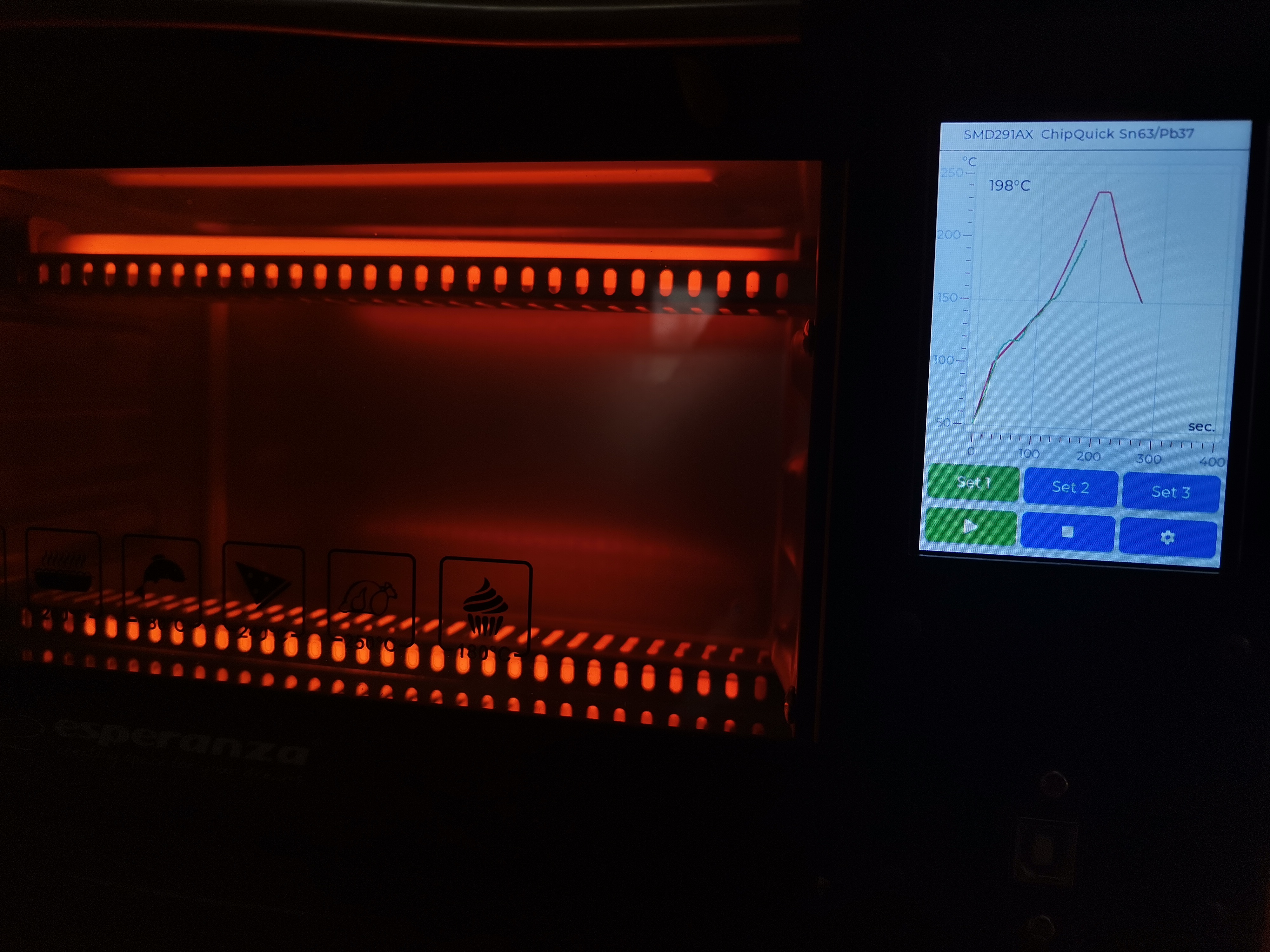 The program allows temperature regulation according to the course of the specified curve for three preset courses, it can be selected using the buttons Set1, Set2, Set3, or in manual mode where the required temperature and required time can be set. The desired thermal curve is defined using the temperature and the specified time for the given temperature type in the files named Set1.txt Set2.txt and Set3.txt. The temperatures and times defined in these files should correspond to the required temperature course for the given type of solder paste. The first and third lines in the file are reserved. The second line contains the name of the solder paste that appears in the top line of the display. The fourth line contains the temperature values in the order in which they should be reached. The 5th line contains the times in seconds and for which the required temperature should be reached. It can be said that it defines the steepness of the temperature rise curve in a certain way. Considering that the device only has heating and not cooling control, to achieve a temperature drop, in case of request controlled drop in temperature, manual intervention in the regulation should be considered by opening or moving the door to achieve the desired drop in temperature. The desired temperature course according to the specified values in the selected Setx file is achieved using the ESP32 Micropython Control Lib PID controller, freely available on github. Pressing a button on the display is signaled by its animation, a change of state is indicated by a color change. For example, if the start button is accepted and the start mode is started, its color changes to green, if the stop button is accepted and the ongoing function is stopped, it is indicated by the color of the Stop button changing to red. The selection of the set or manual button is indicated by the change of color of the corresponding button to green. A failure of the sensor or heating body is indicated by an error message on the screen with blocking of all buttons and their transition to gray color followed by a restart after 10 seconds.
To upload the control program to the microcontroller, it is necessary to first install the MicroPython firmware. This is done via the USB port. It is necessary to have the Thonny program installed. In the Thonny program, in the menu item, open the option item and in the Inperpreter tab, select the MicroPython (ESP32) interpreter type, in the WebREPL section, select the appropriate USB port corresponding to our device, for PC communication with the furnace. By clicking on the item install or update MicroPython(esp32), we call up the option of uploading the firmware to the ER-DIS05035H microcontroller unit. I note that before clicking the Install button, it is necessary to restart the micro controller module into boot mode and this is achieved by pressing the boot button on the micro controller board, holding it down and connecting the power supply. Detailed instructions can be found here. Uploading and running the control program is then easy. The software package contains the main program main.py, the library DFRobotMAX31855.py, which contains the necessary libraries for reading the temperature from the temperature measurement module DFR5508 and the PID controller libraries pid_aw.py and utils_pid_esp32.py.
Setup and revival:
There is no need to perform any other settings regarding the installation of the circuit board of the LK-014 switch and uploading the program package to the microcontroller. Before connecting the LK-014 switch to the microcontroller, it is a good idea to test its function by connecting the output 2 of the X2 terminal block of the LK-014 switch, to a voltage of 0V, or 3V, or 5V and watch whether the LED diode indicating switching activity of the U6 element by lights up, or goes out on the U6 element. If so, you're done.
Conclusion:
You can use the described device not only for soldering SMT printed circuit boards, but also, for example, for drying sprayed photoresist or other substances, for post-processing 3D print, etc., in the temperature range of 50°C to 250°C.