")
")
The basic equipment of every electrical engineering or model maker's workshop includes a mini drill, in the case of electrical engineering primarily for drilling printed circuit boards.

Description:
A seemingly simple operation, drilling holes, has its own hidden pitfalls affecting the quality of the drilled holes in subsequent operations, especially soldering, and therefore has an impact on the overall result. A frequent problem when drilling holes is the need to accurately guide the drill to the axis of the position of the drilled hole, which often slips due to surface irregularities (etching, lack of etching, missing recess for the hole, surface paint irregularities, etc.) into an unwanted position and we drill the hole where we do not want it, or when the drill slides at high speeds on the surface of the board, unpleasant scratches are created, which may not only be cosmetic in nature, but thinner conductive tracks can be damaged.
At low revolutions of the drill, guiding to the correct position is easier and the risk of damage to the surface of the printed circuit board (hereafter PCB) due to slips of the drill at high revolutions is reduced. The drilling of small holes up to a diameter of 1 mm is performed at speeds above 10,000 rpm. The most suitable revolutions depend on the material being drilled, on the type of drill bit used, and in amateur conditions are most often determined by trial and error. For this purpose, it is necessary to have a suitable speed regulation, which is most often solved by regulating the voltage of the mini drill. The vast majority of mini drills have a working voltage in the range of 12V - 20V, which corresponds to a spindle speed of 12000 rpm - 20000 rpm. Solving the above problems helps to solve the described device.
Controller functions.
The device allows you to regulate and control the revolutions of the mini drill by setting the output voltage in the range of 12V - 20V in automatic or manual mode. The overall circuit diagram of the device is in Fig.1.
 In manual mode, the speed of the mini drill is set to a fixed value by adjusting the output voltage using the potentiometer POT1. By pressing the SW1 button, the controller switches to "automatic mode", which is signaled by the lighting of the built-in LED in the button, by applying +24V voltage to the corresponding terminals. Pressing the button repeatedly switches the device to "manual mode", the LED goes out. The resistor needed to limit the LED current in the button is a part of the SW1 element and the part is already supplied with it and therefore it is not even drawn in the diagram in Fig.1, but the LEDpin output of the SW1 switch fitted with this resistor is connected to output 1 of the X5 connector. In automatic mode, the revolutions of the mini drill are low, which will allow easy guidance of the drill into the correct position, when drilling is started, the revolutions of the drill will automatically increase to the value of revolutions corresponding to the setting of potentiometer POT1. After drilling the hole, the speed drops to a low k value and the device is ready to drill the next hole.
Description of the connection.
The overall wiring diagram is shown in Fig.1. The XA1 socket is intended for connecting a movable supply to the 230V network, the main switch SW2 ensures safe switching off and on of the device. Fuse F1 and socket XA1 form one structural element. The 24V voltage source for powering the LK-015 regulator and the mini drill is provided by the PWR power supply module. Potentiometer POT1 adjusts the maximum value of the output voltage. A push-button switch with built-in light signaling ensures the switching of the regulator mode, and the V-meter and A-meter panel gauges display the output voltage and current drawn by the mini drill. The LK-015 regulator block contains electronics ensuring functionality. The circuit diagram of the LK-015 regulator is in Fig.2.  . The supply voltage +24V is supplied to the terminals of the terminal board X1. Capacitors C2 and C3 provide filtering of the input voltage. The 24V input voltage is supplied to the input of the DC-DC converter with PWM modulation U1 (XL4016) operating with a fixed frequency of 180kHz. The desired output voltage at the terminals of the X6 terminal block in the idle state in automatic mode is determined by the size of the resistors R2 and R3 and is set to 3V. When the mini drill is loaded, by pressing on the tip of the drill, the drawn current increases, when its value rises to approximately 0.6V, the transistor U2 (BC237) opens, which connects the series combination of resistors R4 and POT1 in parallel to resistor R2. The result is a change in the dividing ratio of R2` and R3 in the DC-DC converter circuit, where R2` is the resistance value of the series-parallel connection R2, R4 and POT1. The values of these components are set so that the output voltage at the terminals of terminal block X6 is in the range of 12v to 20V with a consumption of approximately 1A. The voltage drop on resistor R6 is led through connector X4 (JST) to the panel meter A-meter, which displays the amount of output current. A panel meter V-meter (DSN-VDM-586) connected to X3 shows the magnitude of the output voltage. With the help of resistors R7, R8, it is possible to adjust the brightness of the panel gauges in a limited range. Panel meters (DSN-VDM-586) are supplied in a two-wire version (the measured voltage is also the supply voltage) for the range of measured voltage 4.5V to 30V and require adjustment so that the display also shows values lower than 4.5V. The modification consists in removing the resistor R3 from the panel meter
  (Fig. 3) and adding a third wire soldered to the VT contact surface. V+ and V- are power contacts and VT (marked as INput in the diagram in Fig. 1) is the measured voltage. All three wires are terminated with a JST connector to connect to the controller board via X3 and X4. The LK-015 regulator according to Fig. 2 is realized on one single-sided PCB Fig. 4 with dimensions of 85mm x 60mm.
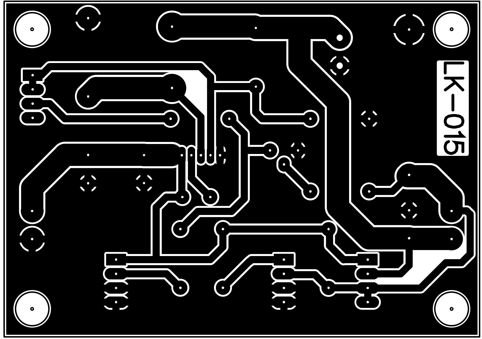

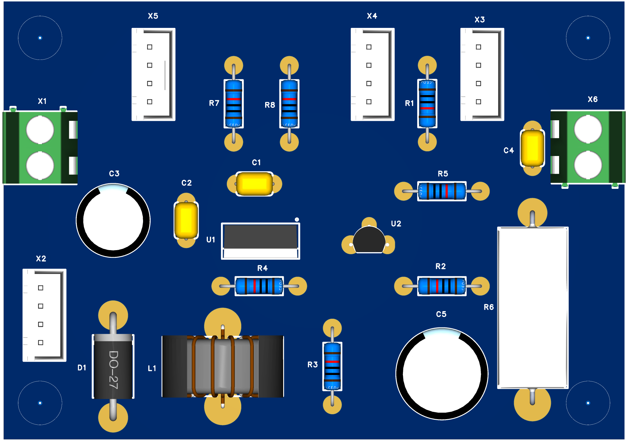
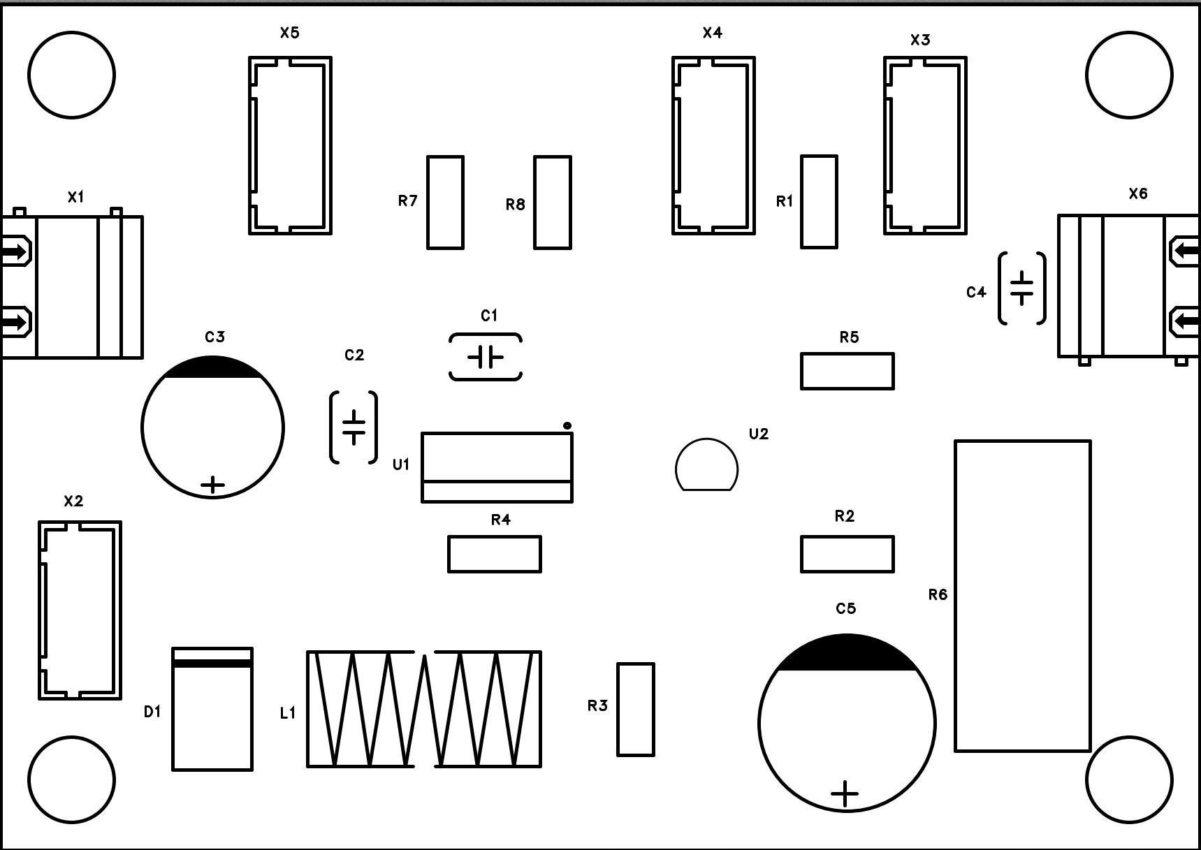
The shape of the plates is chosen taking into account the size of the drilled hole, the current carrying capacity as well as the solderability, so that the copper layer does not peel off from the substrate in the event of possible overheating. The connections are made in a way close to the design of the PCB with dividing lines to minimize the consumption of the etching solution. The layout of the parts is obvious from Fig. 5 and Fig. 6 and does not require further comments. There is no need to make any settings for the revival and everything will work on the first try if the components are connected flawlessly. Even a beginning radio amateur should be able to handle the implementation. Choosing a cabinet to install the regulator will be the least problem. I used a box from an antediluvian BK125 source. A view of the distribution of elements in the cabinet and a view of the finished device is on Fig. 12

Conclusion.
It is also possible to implement an economical functional variant of the regulator by omitting the switch SW1, panel gauges, and the corresponding connectors X3, X4, X5. I believe that this post will be useful for radio amateurs and modelers who want to improve the quality of their products and the equipment of their workshop.
List of used parts:
| No. | Quantity | Comment | Designator | Value | Manufacturer Part | Supplier Part | Supplier |
| 1 | 2 | MER699 | A-meter,V-meter | MER699 | MER699 | MER699 | Techfun |
| 2 | 3 | 100nF | C1,C2,C4 | 100nF | K104K20X7RH53H5 | C1620208 | TME |
| 3 | 1 | 470uF | C3 | 470uF | ICS7576 | ICS7576 | Techfun |
| 4 | 1 | 1000uF | C5 | 1000uF | ICS7571 | ICS7571 | Techfun |
| 5 | 1 | SR560 | D1 | SR560 | SR560 | C331742 | LCSC |
| 6 | 1 | 47uH | L1 | 47uH | SLT050125T470MUB | C326012 | LCSC |
| 7 | 1 | 500R | POT1 | 500R | 6PMI-500R | TME | |
| 8 | 2 | 10K | R1,R3 | 10K | MRS25000C3301FCT00 | LCSC | |
| 9 | 1 | 6K8 | R2 | 6K8 | MRS25000C3301FCT00 | LCSC | |
| 10 | 1 | 680R | R4 | 680R | MRS25000C3301FCT00 | LCSC | |
| 11 | 1 | 3K3 | R5 | 3K3 | MRS25000C3301FCT00 | LCSC | |
| 12 | 1 | 1R | R6 | 1R | CR-L5W2.5R 5% P | LCSC | |
| 13 | 2 | 0R | R7,R8 | 0R | MRS25000C3301FCT00 | LCSC | |
| 14 | 1 | K6-6133D-L1-02 | SW1 | V10F-11Z-230R | V10F-11Z-230R | C128977 | LCSC |
| 15 | 1 | XL4016E1 | U1 | XL4016E1 | XL4016E1 | C55881 | LCSC |
| 16 | 1 | BC237 | U2 | BC237 | BC237 | C3034831 | LCSC |
| 17 | 2 | WJ128V-5.0-2P | X1,X6 | WJ128V-5.0-2P | WJ128V-5.0-2P | C8269 | LCSC |
| 18 | 4 | B4B-XH-AM | X2,X3,X4,X5 | B4B-XH-AM | B4B-XH-AM | 282836-4 | TME |
Useful links:
https://www.tme.eu/sk/details/d-0550/elektricke-naradie/donau-elektronik/0550/?brutto=1¤cy=EUR&gad_source=1&gclid=EAIaIQobChMInNaig_KThAMVMZ1oCR0yVAm1EAQYAiABEgLH2fD_BwE
https://html.alldatasheet.com/html-pdf/1134369/XLSEMI/XL4016/250/1/XL4016.html
https://techfun.sk/produkt/voltmeter-dc-0-56-4-5-30v/
https://www.tme.eu/sk/details/eps-65-24/otvorene-zdroje/mean-well/